How to Diagnose a Failing Industrial PCB Before Calling for Repair
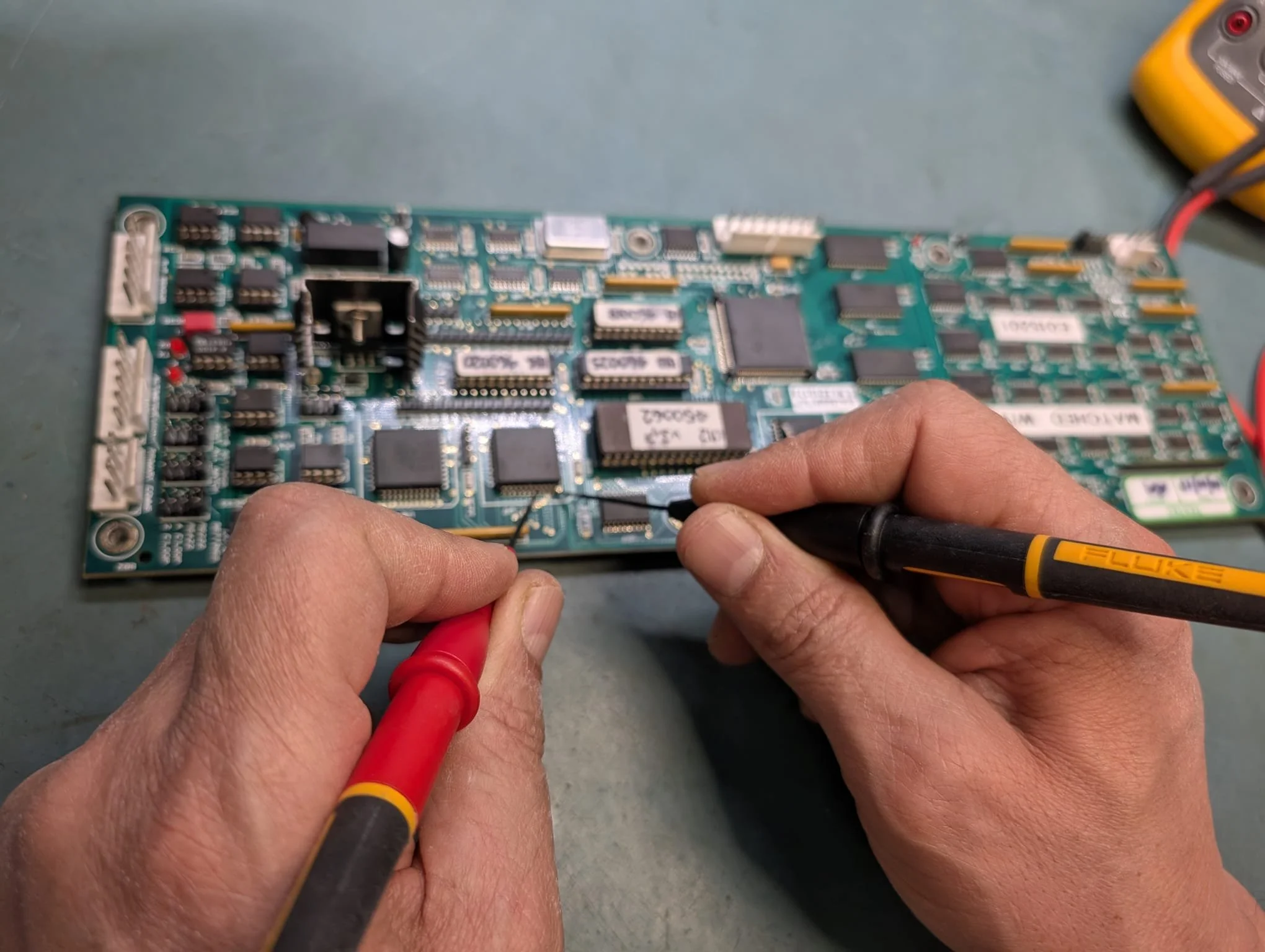
Industrial PCB circuit board showing electronic components for fault diagnosis
Your production line stops. The control panel flashes an error. A technician examines the equipment and points at a circuit board: "PCB failure."
The immediate question: does this need expensive replacement, or can it be repaired?
Before making that call, there are diagnostic steps you can perform yourself. This guide shows you how to identify common PCB faults, what information to gather, and crucially - when DIY troubleshooting ends and professional diagnosis begins.
As ISO 9001 certified electronics repair specialists in Newcastle, we diagnose hundreds of industrial PCB faults annually. Customers who provide thorough diagnostic information receive faster quotes and shorter turnaround times. Here's what you can check safely before contacting a repair company.
Before You Start: Critical Safety Checks
PCB troubleshooting requires strict safety precautions. Industrial electronics contain components that store lethal voltages even after power disconnection.
Essential safety steps:
Isolate equipment from mains power completely
Discharge capacitors using proper procedures (they hold voltage for hours after shutdown)
Use insulated tools only
Never work on live circuits
Wear appropriate PPE
If you're not electrically qualified or lack proper safety training, stop here. Send the board for professional diagnosis. PCB troubleshooting on powered equipment can cause fatal electric shock.
Step 1: Visual Inspection - What to Look For
Remove the PCB from equipment with power fully isolated. Inspect both sides under good lighting, preferably with a magnifying glass or phone camera zoom.
Look for these damage indicators:
Burnt or discolored components: Dark brown or black marks on resistors, integrated circuits, or capacitors indicate overheating or electrical overstress. These components have likely failed.
Cracked solder joints: Common in equipment exposed to vibration (marine vessels, rotating machinery, offshore platforms). Solder joints appear dull, cracked, or separated
from component leads.
Bulging or leaking capacitors: Electrolytic capacitors fail with age. Look for swollen tops, rust-colored residue, or split casings. Equipment over 10 years old frequently shows capacitor deterioration.
Corroded tracks or connectors: Green or white corrosion indicates moisture ingress. Common in marine and offshore electronics exposed to salt spray.
Physical damage: Cracks in the board substrate, broken components, impact marks, or bent connector pins.
Take clear, well-lit photos of any damage from multiple angles. When you contact repair companies, these photos enable immediate initial assessment. We can often confirm repairability and provide ballpark pricing from photos alone.
What visual damage tells you: Burnt individual components are usually repairable through component replacement. Cracked PCB substrate may not be economically viable. Widespread corrosion across multiple areas requires cost comparison against replacement.
Step 2: Check Power Supply Voltages
Basic power supply checks can identify common failure modes without specialized equipment.
What you need: Digital multimeter and equipment manual (if available).
Voltage measurement procedure:
Locate test points or connector pins where DC voltages should be present. These are often marked on the PCB or documented in service manuals.
Measure voltages with equipment powered but PCB removed and isolated. Compare readings against expected values (typically 3.3V, 5V, 12V, 24V in industrial systems).
Record your findings:
No voltage present: Power supply section failure. Often repairable through component replacement (blown fuses, failed regulators, damaged transformers).
Low voltage (example: 3.8V instead of 5V): Indicates failing voltage regulators or degraded filter capacitors. Usually economically repairable.
Correct voltage but equipment still faulty: Logic-level fault requiring professional diagnosis with oscilloscopes and logic analyzers.
What NOT to do: Never apply external power supplies without understanding circuit requirements. Don't probe circuits while powered unless specifically trained. Don't bypass
safety interlocks or protective devices.
Step 3: Assess Operating Environment
Environmental factors significantly influence PCB failure modes and guide repair diagnosis.
Ask these questions:
Where is this equipment located? Marine vessel, offshore platform, factory floor, clean room, outdoor installation?
Temperature exposure? Extreme heat accelerates component aging. Thermal cycling (hot/cold cycles) stresses solder joints.
Vibration levels? Equipment mounted on vessels, vehicles, or near rotating machinery experiences solder joint fatigue.
Moisture exposure? Condensation, humidity, or water ingress causes corrosion and electrical tracking.
Contaminant exposure? Metal dust (machining environments), chemical fumes (production facilities), or salt spray (marine/offshore) damage electronics progressively.
Why environment matters: Repair engineers adjust diagnostic approaches based on operating conditions. Marine electronics require different fault-finding than factory equipment. Environmental information in your repair request reduces diagnostic time by 30-50%.
When to Stop DIY and Call Professionals
DIY diagnosis has clear limits. Professional equipment and expertise become essential when:
You've identified obvious damage but don't know which components to replace or their specifications.
Power supply voltages measure correctly but equipment still doesn't function (indicates logic faults, firmware corruption, or failed microprocessors).
Fault behavior is intermittent - appearing and disappearing randomly. Intermittent faults require extended monitoring with specialized diagnostic equipment.
No schematic or service documentation available. Reverse engineering complex circuits requires professional test equipment.
Equipment is obsolete (15+ years old) and manufacturer support no longer exists.
Multi-layer PCB construction where internal track faults are invisible to visual inspection.
Professional diagnostic advantage: Specialist workshops use ABI BoardMaster in-circuit testing, thermal imaging cameras, and oscilloscopes to locate faults DIY methods cannot detect. We achieve 85%+ diagnostic success rates within 1-2 days, including boards without manufacturer documentation.
For obsolete equipment, we reverse-engineer circuits using component signature analysis and repair systems where original manufacturers no longer exist.
What Information Speeds Professional Repair
When contacting repair companies, detailed information significantly reduces turnaround time.
Provide these details:
Equipment identification: Manufacturer name, model number, serial number. PCB part number (usually printed on the board).
Equipment age and operating environment (marine, offshore, manufacturing, outdoor, etc.).
Fault description: When did failure occur (sudden or gradual deterioration)? What error messages displayed? What was equipment doing when it failed (normal operation, power surge, after maintenance)? Is the fault permanent or intermittent?
Your diagnostic findings: Photos of damaged components from multiple angles. Voltage measurements you recorded. Environmental factors you identified.
Why detail matters: Comprehensive information reduces our diagnostic time by 30-50%. We can begin sourcing long-lead-time obsolete components while your board is in transit, reducing total turnaround from 10 working days to 5 days.
Get Professional Assessment
Industrial PCB troubleshooting starts with safe visual inspection and basic voltage checks. These diagnostic steps help determine fault severity and provide repair companies with information that accelerates professional diagnosis.
Complex faults - intermittent problems, logic errors, firmware issues, and multi-layer board failures - require professional diagnostic equipment and specialist expertise that DIY methods cannot replicate.
Diagnosed a PCB fault but unsure if it's repairable? Send us photos and a detailed fault description for free initial assessment. We respond within 24 hours with repairability confirmation and estimated turnaround time.
Call 0800 001 6045 or submit a repair request through our Customer Portal.
Northern Power Electronics - Based in Newcastle upon Tyne - Serving UK manufacturing, marine, and offshore industries - ISO 9001 certified electronics repair specialists.